HOW TO DRIVE THE LCD
Static Drive LCD Technology
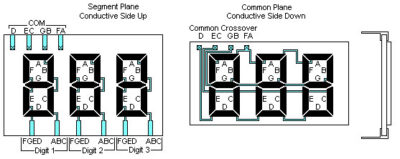
The configuration for Liquid Crystal Display Static Drive technique is that one side of all of the Liquid Crystal Display segments are tied to a common, or backplane, and the other side of each of the segments are routed to individual connection points that are tied to the driver control circuitry. This method uses a large number of interconnects and is not feasible for complex displays, but it does produce the best looking display

LCD’s require an AC drive voltage with virtually no DC component. Segments are controlled by the magnitude of the AC voltage across the LCD segment, but there must always be AC voltage across ALL segments of the LCD. Prolonged DC operation may cause electrochemical reactions inside the displays which will cause significantly reduced life. The initial indications of display degradation because of excessive DC current is a loss of alignment along the edges of some of the characters. The visual indication will be a “fuzzy” appearance of some of the characters.
The TN LCD is an RMS voltage responsive device, that is, the contrast of a given segment is dependent upon the RMS value of the applied voltage across it, measured with respect to the common plane. This fact, which seems obvious now, is very important when discussing drive schemes.
Drive frequencies for direct drive displays are typically between 30Hz and 100Hz. Depending on the display size and design, displays can be operated at higher frequencies, but this will result in increased power consumption. LCDs portray a capacitive load, which reduces the load impedance as frequency increases. However, operation below 30Hz typically results in display flicker
LCD’s can be overdriven by a combination of voltage and frequency, which will result in cross talk or “ghosting”. Ghosting is the appearance or partial activation of an “off” segment. This condition occurs when high drive voltage and frequency are applied. Since the current is directly proportional to the frequency, there is a voltage-frequency product which must not be exceeded. These values are very dependent on the design and layout of any given part, so proper display design and choice of driving conditions is important. It is also very important that all unused segments be connected to the backplane, and not allowed to float.
Multiplex Drive LCD Technology
The configuration for Liquid Crystal Display Multiplex Drive technique differs from a Static Drive technique is that it uses more than a single”backplane” or segment common. With this configuration, each segment control line can be connected to as many segments as there are backplanes, providing that each of the segments that it is connected to are tied to a separate backplanes. This method “Multiplexes” each of the segment control lines and minimizes the number of interconnects. This is the method used with complex displays that have limited interconnection surface area or available drive circuits. This reduction in the number of external connections enhances device reliability and increases the potential display density. The liability of a higher multiplex rate will effect display quality, operational temperature range, and the increased complexity of drive circuitry (or perhaps microprocessor software) may necessary for their operation.

The method of drive for multiplexed displays is essentially a time division multiplex with the number of time divisions equal to twice the number of common planes used in a given format. As is the case with conventional LCDs, in order to prevent irreversible electrochemical action from destroying the display, the voltage at all segment locations must be caused to reverse polarity periodically so that zero net DC voltage is applied. This is the reason for the doubling in time divisions: Each common plane must be alternately driven with a voltage pulse of opposite polarity.
As is the case with non multiplexed displays, the drive frequency should be chosen to be above the flicker-fusion rate, i.e. >30 Hz. Since increasing the drive frequency significantly above this value increases current demand by the CMOS drive electronics, and to prevent problems due to the finite conductivity of the display segment and common electrodes, an upper drive frequency limit of 60-90 Hz is recommended.
